
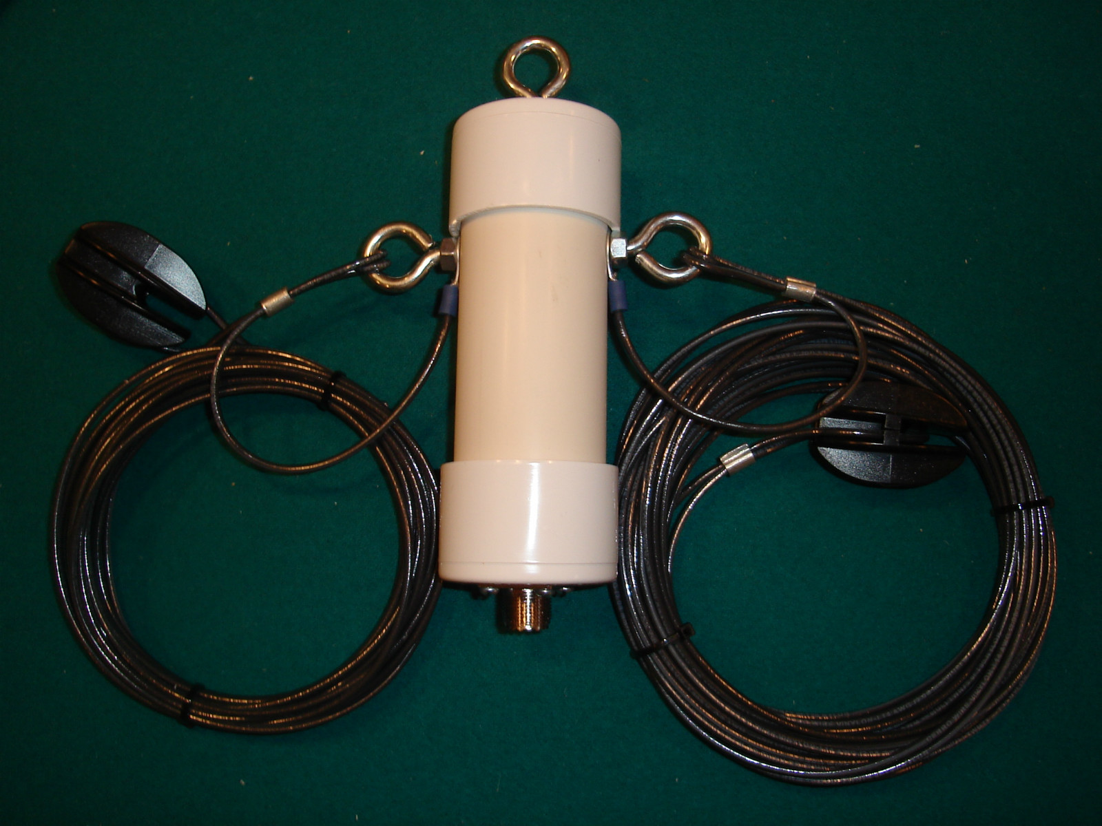
So I have to admit I don’t have my HF/HAM radio yet, but it’s on my Christmas list. I have my eyes set on a radio a little more powerful than a handheld HF; so we’ll see what my wife says. However, I do have my dipole antenna ready to go (a little backwards, I know). I set up this antenna configuration after talking with several subject matter experts I work with, and it was the antenna system they all recommended as being the most effective.
A LTC (lieutenant colonel) who is an amateur radio enthusiast talked about our last deployment where he had brought along his HAM radio and set up a dipole that let him talk with people from South America to the South Pacific, all the way from a system that could pack into a shoebox in Iraq. He tells me people now days don’t realize how easily our internet and phones can go down in a mild emergency situation. Another SSG (staff sergeant) I work with says the beauty of dipole antennas is how versatile and easily constructed they are; he says you are only limited by your imagination as to the materials that can be utilized.
So what is a dipole antenna? According to Wikipedia; in radio and telecommunications a dipole antenna or doublet is the simplest and most widely used class of antenna. It consists of two identical conductive elements such as metal wires or rods, which are usually bilaterally symmetrical. The driving current from the transmitter is applied, or for receiving antennas the output signal to the receiver is taken, between the two halves of the antenna. Each side of the feedline to the transmitter or receiver is connected to one of the conductors. This contrasts with a monopole antenna, which consists of a single rod or conductor with one side of the feedline connected to it, and the other side connected to some type of ground. A common example of a dipole is the “rabbit ears” television antenna found on broadcast television sets.
The most common form of dipole is two straight rods or wires oriented end to end on the same axis, with the feedline connected to the two adjacent ends. This is the simplest type of antenna from a theoretical point of view. Dipoles are resonant antennas, meaning that the elements serve as resonators, with standing waves of radio current flowing back and forth between their ends. So the length of the dipole elements is determined by the wavelength of the radio waves used. The most common form is the half-wave dipole, in which each of the two rod elements is approximately 1/4 wavelength long, so the whole antenna is a half-wavelength long. The radiation pattern of a vertical dipole is omnidirectional; it radiates equal power in all azimuthal directions perpendicular to the axis of the antenna. For a half-wave dipole the radiation is maximum, 2.15 dBi perpendicular to the antenna axis, falling monotonically with elevation angle to zero on the axis, off the end of the antenna.
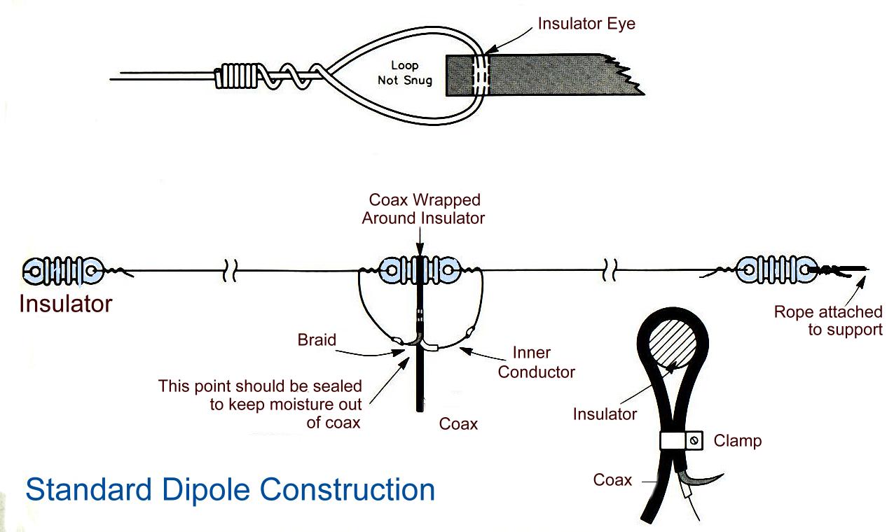
Horizontal wire dipole antennas are popular for use on the HF shortwave bands, both for transmitting and shortwave listening. They are usually constructed of two lengths of wire joined by a strain insulator in the center, which is the feedpoint. The ends can be attached to existing buildings, structures, or trees, taking advantage of their heights. If used for transmitting, it is essential that the ends of the antenna be attached to supports through strain insulators with a sufficiently high flashover voltage, since the antenna’s high voltage antinodes occur there. Being a balanced antenna, they are best fed with a balun in between the (coax) transmission line and the feedpoint.
These are simple to put up for temporary or field use. But they are also widely used by radio amateurs and short wave listeners in fixed locations due to their simple (and inexpensive) construction, while still realizing a resonant antenna at frequencies where resonant antenna elements need to be of quite some size. They are an attractive solution for these frequencies when significant directionality is not desired, and the cost of several such resonant antennas for different frequency bands, built at home, may still be much less than a single commercially produced antenna.
Below are some terms to know:
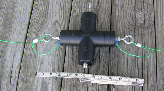
A balun is an electrical device that converts between a balanced signal (two signals working against each other where ground is irrelevant) and an unbalanced signal (a single signal working against ground or pseudo-ground). A balun can take many forms and may include devices that also transform impedances but need not do so. Transformer baluns can also be used to connect lines of differing impedance. The origin of the word balun is “balanced to unbalanced”.
Coaxial cable, or coax, is a type of cable that has an inner conductor surrounded by a tubular insulating layer, surrounded by a tubular conducting shield. Many coaxial cables also have an insulating outer sheath or jacket. The term coaxial comes from the inner conductor and the outer shield sharing a geometric axis. Coaxial cable differs from other shielded cable used for carrying lower-frequency signals, such as audio signals, in that the dimensions of the cable are controlled to give a precise, constant conductor spacing, which is needed for it to function efficiently as a radio frequency transmission line.
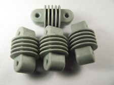
A strain insulator is an electrical insulator that is designed to work in mechanical tension (strain), to withstand the pull of a suspended electrical wire or cable. They are used in overhead electrical wiring, to support radio antennas and overhead power lines. A strain insulator may be inserted between two lengths of wire, to isolate them electrically from each other while maintaining a mechanical connection, or where a wire attaches to a pole or tower, to transmit the pull of the wire to the support while insulating it electrically.
An important consideration is the length of your antenna, as it has to match your desired frequency wave length. There is some power lost in the cable running from the radio to the balun; but if you do the math you will discover it is negligible.
http://www.csgnetwork.com/antennaedcalc.html
Jon
Leave a Reply